Practical absorbance and fluorescence spectroscopy
The study of electronic transitions to quantify a species is not new, it has been used in many different forms for a number of years. The measurements of absorption of light is based solely on the absorbing of photons, fluorescence measures the emission of photons after absorption.
Absorption spectroscopy introduction
The absorbing of a photon by a chromophore occurs readily in almost all chemical species. If it can be seen then it absorbs light, if it is transparent it is still absorbing radiation but most likely in the ultraviolet or visible light range.
The colours that are represented are seen across the visible light spectrum although this does not quantify all the colours our eyes can see, a mixture of different wavelengths can allow a different perception of what a colour is.
So what happens when a photon is absorbed? Usually the energy is lost as heat. This is why black objects are hotter than white objects, all of the photons are being absorbed in one and producing heat this is through radiation.
Fluorescence spectroscopy introduction
The fluorescence of a species is where the absorbed radiation is then re-emitted at a different wavelength. Most things do not fluoresce as it is only necessary when the ability to remove energy through heat and vibrations cannot occur.
Beer-Lambert law
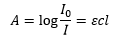
The ability for a sample to absorb a photon can be quantified through the Beer-Lambert law. This is where I0 and I are the initial and final intensity values respectively. This is obtained experimentally through the comparison of the absorbance A and normalising the concentration and path length.
Absorption spectroscopy introduction
The absorbing of a photon by a chromophore occurs readily in almost all chemical species. If it can be seen then it absorbs light, if it is transparent it is still absorbing radiation but most likely in the ultraviolet or visible light range.
The colours that are represented are seen across the visible light spectrum although this does not quantify all the colours our eyes can see, a mixture of different wavelengths can allow a different perception of what a colour is.
So what happens when a photon is absorbed? Usually the energy is lost as heat. This is why black objects are hotter than white objects, all of the photons are being absorbed in one and producing heat this is through radiation.
Fluorescence spectroscopy introduction
The fluorescence of a species is where the absorbed radiation is then re-emitted at a different wavelength. Most things do not fluoresce as it is only necessary when the ability to remove energy through heat and vibrations cannot occur.
Beer-Lambert law
The ability for a sample to absorb a photon can be quantified through the Beer-Lambert law. This is where I0 and I are the initial and final intensity values respectively. This is obtained experimentally through the comparison of the absorbance A and normalising the concentration and path length.
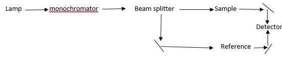
The spectrometer needs to measure the lamp intensity at each wavelength. The sample and reference beams are compared giving the two different intensities. This can be used to either give data about the solvent and the analyte by comparison of the two or it can be used to gain the results of just the analyte.

The extinction coefficient ε can be determined from the experimentally determined absorption. This can give a good idea of what sort of bond transition is occurring.
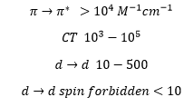
The transitions can be a quick way of identifying what type of molecule it is that is present. A metal centre with many ligands present can be involved in both Charge Transfer and d→d transitions. By calculating the extinction coefficient and corresponding to each transition a prediction can be made at the type of bonding in that structure.
Radiation sources
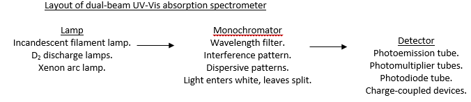
Radiation sources are found in a number of different variants. It is important that the radiation source maintains a steady intensity for each wavelength over time. It does not matter if the intensity varies from one wavelength to another just so long as the intensity does not vary in the same wavelength.
Incandescent filament lamps
Rugged, stable and cheap but not very bright.
The incandescent filament lamps used act as black body radiators. The issue with incandescent filament lamps is that they only 15% of light is in the visible range at 3000 K. This can give issues as the main radiation is in the NIR range, UV can be blocked easily by the glass envelope. Although the temperature can be changed to produce radiation from 350-2500 nm. An issue is when the temperature is increased above 3000 K tungsten sublimes and reacts with the glass envelope degrading the filament and making the envelope opaque. This means the lamp becomes useless over time.
This can be avoided by using tungsten-halogen lamps. These lamps have added iodine vapour at high pressure. This reacts with the sublimed tungsten and re-deposits it on the metal. This means that the intensity stays high at >90% over the life time. Quartz walls are used due to high temperatures.
D2 discharge lamps
These are deuterium lamps that are sometimes called arc discharge lamps. The low-pressure gas discharge light source for use in UV region. The lamp contains gas at low pressure. The source of light is between the nickel cathode and the anode. The light radiation does not come from the heated sources it comes from the plasma in the middle. This is produced through an aperture through a window. This only needs a small voltage of around 40V. Due to high temperatures and wavelengths a fused quartz UV glass or magnesium fluoride envelope is required.
These discharge lamps produce a continuum in the UV into the visible. Although there is a sharp intensity drop off there is still a large relative intensity in the visible light region. At the very low pressures it is possible for large intensity spikes to occur across the visible region from single ions.
Xenon arc lamps
High intensity across UV/Vis range, very expensive, produces reasonably smooth continuous spectrum. Works from 300-1300 nm although they are highly expensive under a high pressure.
Mercury discharge lamp
The mercury discharge lamp works by producing a large amount of ultraviolet light. This can then be floursed into the visible light spectrum by phosphored and non-phosphored groups.
Wavelength selection
Spectrophotometric measurements usually require the isolation of discrete bands of radiation. This can be carried out by filters or monochromators or both, usually both.
Filters
Filters are used to allow different wavelengths of light. These are useful as they can allow around 80% of a select wavelength blocking nearly 100% of another wavelength. They can also be used in conjunction with one another to create a wide band gap and a narrow band gap filter. These are sometimes used to produce a more efficient splitting later on.
Interference filters can also be used. These have a partially reflective surface that causes sections of light to be transmitted back depending on how many times the light is reflected across the membrane depends on its wavelength and how many times it has been reflected in the system. When these ossilate it produces a multiple splitting pattern. The transmission peaks can be made sharper by increasing surgace reflectivity. Sharpness is defined by full width at half maximum height.
Monochromators
Monochromators is to provide a beam of radiant energy of a given nominal wavelength and spectral bandwidth. Monochromators consist of:
· An entrance slit that provides a narrow optical image of the radiation source.
· A collimator that rendrs parallel radiation emanating from the entrance slit.
· A grating or prism for dispersing incident radiation.
· A collimator to reform images of the entrance slit on an exit slit.
· An exit slit to isolate the desired spectreal band by blocking all of the dispersed radiation except that wihin the desired wavelength.
The monochromator needs to have: design simplicity, resolution, spectral range, purity of exiting radiation, dispersion.
Dispersive elements are very important and consist of narrow, closely spaced parallel slits. These cause light to diffract according to its wavelength. It is important to remember that there is 0 order white light. 1st order diffraction and then 2nd order diffraction occurs. The second order diffraction can overlap with the first order causing interference.
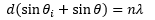
The angles needed to cause constructive interference are related to the initial radiation wavelength by an integer. This means that the light emerges from the adjacent slits is
Reflection diffraction patterns are normally used in monochromators. These utilise a series of narrow grooves on a reflective substrate. Each groove produced a different wave depending on the incident angle. Which is then modified with the equation.
Radiation sources are found in a number of different variants. It is important that the radiation source maintains a steady intensity for each wavelength over time. It does not matter if the intensity varies from one wavelength to another just so long as the intensity does not vary in the same wavelength.
Incandescent filament lamps
Rugged, stable and cheap but not very bright.
The incandescent filament lamps used act as black body radiators. The issue with incandescent filament lamps is that they only 15% of light is in the visible range at 3000 K. This can give issues as the main radiation is in the NIR range, UV can be blocked easily by the glass envelope. Although the temperature can be changed to produce radiation from 350-2500 nm. An issue is when the temperature is increased above 3000 K tungsten sublimes and reacts with the glass envelope degrading the filament and making the envelope opaque. This means the lamp becomes useless over time.
This can be avoided by using tungsten-halogen lamps. These lamps have added iodine vapour at high pressure. This reacts with the sublimed tungsten and re-deposits it on the metal. This means that the intensity stays high at >90% over the life time. Quartz walls are used due to high temperatures.
D2 discharge lamps
These are deuterium lamps that are sometimes called arc discharge lamps. The low-pressure gas discharge light source for use in UV region. The lamp contains gas at low pressure. The source of light is between the nickel cathode and the anode. The light radiation does not come from the heated sources it comes from the plasma in the middle. This is produced through an aperture through a window. This only needs a small voltage of around 40V. Due to high temperatures and wavelengths a fused quartz UV glass or magnesium fluoride envelope is required.
These discharge lamps produce a continuum in the UV into the visible. Although there is a sharp intensity drop off there is still a large relative intensity in the visible light region. At the very low pressures it is possible for large intensity spikes to occur across the visible region from single ions.
Xenon arc lamps
High intensity across UV/Vis range, very expensive, produces reasonably smooth continuous spectrum. Works from 300-1300 nm although they are highly expensive under a high pressure.
Mercury discharge lamp
The mercury discharge lamp works by producing a large amount of ultraviolet light. This can then be floursed into the visible light spectrum by phosphored and non-phosphored groups.
Wavelength selection
Spectrophotometric measurements usually require the isolation of discrete bands of radiation. This can be carried out by filters or monochromators or both, usually both.
Filters
Filters are used to allow different wavelengths of light. These are useful as they can allow around 80% of a select wavelength blocking nearly 100% of another wavelength. They can also be used in conjunction with one another to create a wide band gap and a narrow band gap filter. These are sometimes used to produce a more efficient splitting later on.
Interference filters can also be used. These have a partially reflective surface that causes sections of light to be transmitted back depending on how many times the light is reflected across the membrane depends on its wavelength and how many times it has been reflected in the system. When these ossilate it produces a multiple splitting pattern. The transmission peaks can be made sharper by increasing surgace reflectivity. Sharpness is defined by full width at half maximum height.
Monochromators
Monochromators is to provide a beam of radiant energy of a given nominal wavelength and spectral bandwidth. Monochromators consist of:
· An entrance slit that provides a narrow optical image of the radiation source.
· A collimator that rendrs parallel radiation emanating from the entrance slit.
· A grating or prism for dispersing incident radiation.
· A collimator to reform images of the entrance slit on an exit slit.
· An exit slit to isolate the desired spectreal band by blocking all of the dispersed radiation except that wihin the desired wavelength.
The monochromator needs to have: design simplicity, resolution, spectral range, purity of exiting radiation, dispersion.
Dispersive elements are very important and consist of narrow, closely spaced parallel slits. These cause light to diffract according to its wavelength. It is important to remember that there is 0 order white light. 1st order diffraction and then 2nd order diffraction occurs. The second order diffraction can overlap with the first order causing interference.
The angles needed to cause constructive interference are related to the initial radiation wavelength by an integer. This means that the light emerges from the adjacent slits is
Reflection diffraction patterns are normally used in monochromators. These utilise a series of narrow grooves on a reflective substrate. Each groove produced a different wave depending on the incident angle. Which is then modified with the equation.
The use of the blazing effect, the rapid grating of a surface, causes no secondary peaks to form.
Prism
A prism can be used to refract light and split it into its own wavelengths this is useful as it allows a high light throughput although it tends to absorb in far UV and Far IR range. It does though have good throughput at 390-1000 nm and has no higher orders.
Slits
Slits can be used to adjust the energy throughput. The image of the entrance slit is kept constant and allows the inlet of light into the monochromator. The exit slit is normally changed to allow a different amount of light to pass. This is done by altering its width.
Slit width controls spectral bandwidth (range of wavelengths passed). Excessivley wide slits, with consequently large spectral bandwidths compromise resolution. With a small slit width the signal to noise ratio increases.
As the lamp produces many different wavelengths of light this needs to be split using gratings this can then be passed through a slit. This leaves the criteria of a monochromator to be based on three factors:
· Resolution: The ability to distinguish adjacent features depends on the degree of wavelength dispersion and the perfection of the image formation.
· Purity: Of the radiation output is determined by the amount of stray or scattered radiation.
· Light gathering power: Is improved by the source and how narrow slits can be used to maintain resolution.
Monochromator output is characterised by:
Central wavelength: λ. Bandwidth Γ, output intensity I. Ideally the bandwidth needs to be small but the intensity needs to be high. This gives the most accurate reading at a certain wavelength. With an increase in bandwidth there is band distortion but a lower signal to noise ratio.
Dispersion
Dispersion is realted to the final point well, this is the degree of separation and the mixing of wavelengths. This is achieved with either a grating or a prsim but there is a collimator at either end. This causes the non-parallel light beams produced after separation to be made parallel to one another again.
This is given the the linear reciprocal dispersion value D-1 this is the number of wavelengths that occur in a certain amount of space.
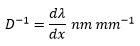
The dispersion can be given by:

This is where f is the focal length of the monochromator. This is the distance from the disperser to the slit. It is better if this is long but that produces a larger chromator which is unfavourable.
Resolution
The resolution or resolving power of a monochromator is its ability to distinguish, as separate entities, adjacent spectral features such as absorption bands. Resolution is determined by the size and dispersing characteristics of a grating or prism and the exit slit width of the monochromator.
Resolution is defined by the equation:

This is where λ is the average wavelength between two lines just resolved dλ is the wavelength difference of these lines.
In principle R varies with slit width.
In principle R varies with slit width.
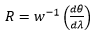
Where w is the slit width. This shows that there is an increase in resolution with a decrease in slit width. R is normally only a theoretical value due to issues with optical aberrations and imperfections.
Large dispersion and high resolving power are necessary in monochromators to measure accurately emission spectra with discrete lines or sharp absorption lines.
Radiation gathering power
Using narrow bandwidths increases resolution. This is due to the wavelengths being under a greater control and being able to be resolved with greater ease. This decreases the signal to noise ratio. This means the monochromator needs to collect as much light as possible the f/number is the ability of the collimator to collect light emerging from the entrance slit.
Sufficient radiation must enter the detector to enable the singal to be distinguished from the back ground. This f/number is an indication of the ability of the collimator mirror to collect radiation that emerges from the entrance slit.
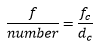
This is where the fc is the focal length and dc is the diameter of the collimator mirror. The smaller the f number the greater the radiation gathering ability.
Detectors
A transducer that converts electromagnetic radiation into an electron flow which can be measured as a current or voltage is the basis of a detector.
They must have:
· Response over a large band width.
· Sensitive to low levels of radiation
· Short response time.
· Essential that signal is directly proportional to beam power
All photon detectors are based on the fact that metal interactions with UV-vis and infrared photons can cause emission of photoelectrons.
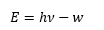
The photoelectric effect is an important process used in most detectors. When radiation hits a metal surface under a potential difference and electron can be removed from this surface. The electron removed can then be measured and a current obtained. The are not released unless the energy of the photons are above a certain value, the work function. Once the photons have the desired energy then the number of photons emitted are directly proportional to the intensity of the photons. There are some good animations on this effect.
This is based on the photoelectric effect where the energy of the emitted photoelectrons is related the energy of the photons and the work function.
Detectors
A transducer that converts electromagnetic radiation into an electron flow which can be measured as a current or voltage is the basis of a detector.
They must have:
· Response over a large band width.
· Sensitive to low levels of radiation
· Short response time.
· Essential that signal is directly proportional to beam power
All photon detectors are based on the fact that metal interactions with UV-vis and infrared photons can cause emission of photoelectrons.
The photoelectric effect is an important process used in most detectors. When radiation hits a metal surface under a potential difference and electron can be removed from this surface. The electron removed can then be measured and a current obtained. The are not released unless the energy of the photons are above a certain value, the work function. Once the photons have the desired energy then the number of photons emitted are directly proportional to the intensity of the photons. There are some good animations on this effect.
This is based on the photoelectric effect where the energy of the emitted photoelectrons is related the energy of the photons and the work function.
When a photoemissive tube is operated in darkness a current still flows, this is called the dark current. It is due to:
· Thermonic emission from photocathode.
· Field emission- caused by high voltage drawing electrons away.
· Ohmic leakage- conduction through tube base.
· Natually occurring radioactivity.
The dark current limits the sensitivity of the detector. When this is added to the shot noise it can produce many issues in the spectrum. This can be overcome by cooling the photoemission tube and by reducing the operating voltage, the operating voltage should be increased until saturation and then turned down to just under that current is then independent of voltage but directly proportional to radiant power.
Another way to increase the signal to noise ratio is to have a pre-amplifier this works by being directly attached to the photoemission tube and amplifying all of the signals immediately. Although this increases the initial noise readings the travel of the signal down wires is less effected by shot noise and is still accurate.
Photoemissive tube
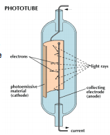
A photoemissive tube is one where there is a simple photocathode-anode combination contained in an evacuated tube. Typically the cathode is a half cylinder of method surrounding a wire anode. As radiation hits the cathode electrons are expelled onto the anode producing a current. Electrons are emitted here by the photoelectric effect.
· Thermonic emission from photocathode.
· Field emission- caused by high voltage drawing electrons away.
· Ohmic leakage- conduction through tube base.
· Natually occurring radioactivity.
The dark current limits the sensitivity of the detector. When this is added to the shot noise it can produce many issues in the spectrum. This can be overcome by cooling the photoemission tube and by reducing the operating voltage, the operating voltage should be increased until saturation and then turned down to just under that current is then independent of voltage but directly proportional to radiant power.
Another way to increase the signal to noise ratio is to have a pre-amplifier this works by being directly attached to the photoemission tube and amplifying all of the signals immediately. Although this increases the initial noise readings the travel of the signal down wires is less effected by shot noise and is still accurate.
Photoemissive tube
A photoemissive tube is one where there is a simple photocathode-anode combination contained in an evacuated tube. Typically the cathode is a half cylinder of method surrounding a wire anode. As radiation hits the cathode electrons are expelled onto the anode producing a current. Electrons are emitted here by the photoelectric effect.
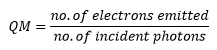
The number of electrons emitted is in direct proportion to the number of photons that strike the surface of the cathode. This can be represented by the qunatum efficiency of the surface. A high efficiency is good as this gives a more accurate reading.
Photomultiplier tube
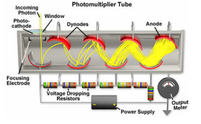
The photomultiplier tube is a combination of a photoemissive cathode and a number of dynodes placed after this. Each dynode is kept at around 90V more positive than the previous causing the electrons to move rapidly coming into conatact with the photoemissive material on each dynode. This has the appility to release more and more electrons. 1 electron can produce around 100,000 further photoelectrons.
This system is very sensitive and has a very low response time of 1ns. An issue is the effect of noise being multiplied by a large amount in this system.
Photodiodes
Photodiodes are made of a planar diffused silicon p-n junction. These are solid-state devices and are fabricated directly onto a silicon wafer. Photons impacting with the diode promote electrons to a conduction band. These are all semiconductors. Most detect only visible/NIR radiation but some UV. These are not as sensitive as photomuliplier tubes although they are very cheap.
Charge coupled devices
Extremely small devices are possible- diode arrays can be made which can record several signals simultaneously. Capable of obtaining a full spectrum within a few milliseconds this is a rapid method of analysis. Charges generated by the photons can be later be read out. The CCD outperform PMTs they are small in size and robust but have the same band width issues as photodiodes.
